| View previous topic :: View next topic |
| Author |
Message |
colbysmith
Joined: 02 Oct 2011
Posts: 4968
City/Region: Madison
State or Province: WI
C-Dory Year: 2009
C-Dory Model: 25 Cruiser
Vessel Name: C-Traveler
Photos: C-Traveler and Midnight-Flyer
|
 Posted: Fri Jul 19, 2024 9:59 pm Post subject: Yamaha's Alternate Charging System Posted: Fri Jul 19, 2024 9:59 pm Post subject: Yamaha's Alternate Charging System |
 |
|
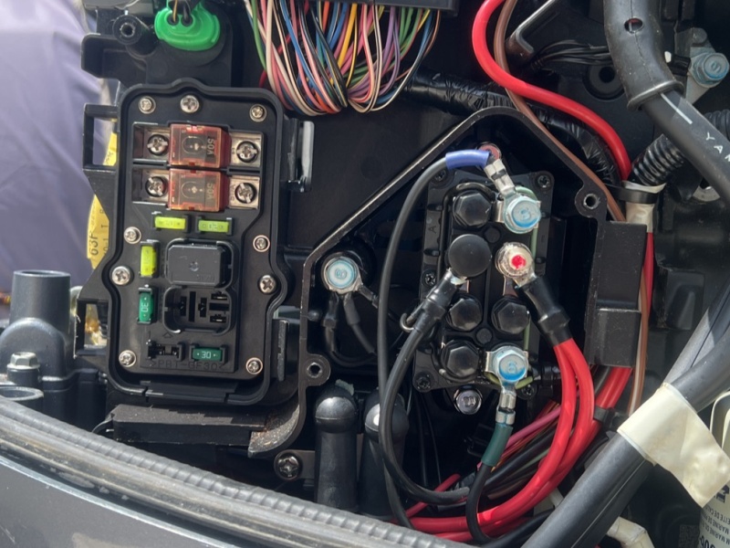
The photo above is at the front port side of my 2009 Yamaha F150 4-stroke outboard. The fuse panel and wiring terminals are behind a plastic shield. My outboard has an alternate charging system, in addition to the regular system from the alternator. Dont ask me how it works, I dont have a clue. The two red wires at the wiring terminal appear to go to the alternator and to the alternate charging lead. The two large red fuses in the fuse block at the left, are 50 amp fuses, and the top one appears to be for the alternate charging system.
So heres the deal. The normal alternator appears to be putting out about 14.5 volts at the batteries, at the second or lower red fuse in the left fuse block, and at the red wires terminal at that wiring terminal on the right. (When the batteries are somewhat discharged, then the voltage drops to about 13.5 volts.) However, the top fuse, and the alternate charging lead at the battery is showing about 15.5 volts when the battery is connected. It drops back down to just a bit over 12 volts when I disconnect the battery. I am reading voltage from my Vectron Battery Monitor, the Digital Engine gauge and a separate VOM, with the engine at idle, and also at around 1000 rpm.
The alternate charging lead is hooked to my starting battery and unless I trip the breaker near the battery in that lead, that battery is always getting charged thru the alternate system. That would be battery 2. My house battery is battery 1. If I have the batteries isolated, ie, battery switch to battery 1, then Im seeing that 15.5 vts on my starting battery. If I go to both, or battery 2 (thereby bringing both the regular and alternate systems into battery 2) it seems to even the voltage out back to about 14.5 volts if the batteries are charged, or 13.x when they are being charged. If I select battery 1, the house battery, then I will see the normal voltage of 14.5 on it, but battery 2 with the alternate charging system is back at about 15.5 volts.
I believe 15 + volts is probably a bit too high for my standard lead acid batteries. I spoke with a mechanic last week, and he felt it was probably a bad regulator/rectifier. Well I just replaced that today with a brand new one, and Im getting the same readings, so thinking then that the voltage regulator/rectifier is good. But still concerned about the higher voltage output on the alternate charging side.
Does anyone have experience with Yamahas alternate charging system, know anything about it, or if voltage of 15.5 volts is good for my lead acid starting battery? I am leaning towards just removing the alternate charging system by leaving the CB tripped at battery 2, and using my 1,2,both battery switch for charging my start battery. Colby |
|
| Back to top |
|
 |
Robert H. Wilkinson
Joined: 26 Jan 2011
Posts: 1278
City/Region: Port Ryerse
State or Province: ON
Vessel Name: Romakeme IV
Photos: Romakeme IV
|
| Posted: Fri Jul 19, 2024 11:11 pm Post subject: |
|
|
Colby, don't know a lot about how your system is wired but have learned a thing or 2 about charging and maintaining wet cells - having lived off grid since 79. A low battery usually starts charging around 13.5v. - and as battery fills amps will taper off and voltage should be held between 14.5 and 15v(per manufacturers spec) for duration of absorption stage. After a predetermined length of time(again per specs) the voltage should be lowered to around 13.8 for the final float stage. Battery should then be fully charged. This ideal charge profile cannot however be obtained with a normal stock alternator.
Re. your question about 15.5v - that is bordering on an equalization charge. My home bank(L16 Surrettes) is purposely charged @ 16v every 30 cycles. This equalizes the cell voltages and keeps them from getting sulfated. Constant charging @ 15.5v will boil the electrolyte and batteries will require frequent watering.
If that battery is already sulfated then its resistance will be high and it won't accept the amps needed for a full charge. This will cause the voltage to spike prematurely. Check that it is good.
Combining a fully charged battery and a discharged one will average the voltages. They should not be combined to charge - one will be overcharged and the other undercharged. They will both end up failing.
Good luck,
Rob
_________________
Talk to me and I will listen-- but if its not about boats or fishing all I will hear is bla,bla,bla,yada,yada,zzzzzzzz |
|
| Back to top |
|
|
colbysmith
Joined: 02 Oct 2011
Posts: 4968
City/Region: Madison
State or Province: WI
C-Dory Year: 2009
C-Dory Model: 25 Cruiser
Vessel Name: C-Traveler
Photos: C-Traveler and Midnight-Flyer
|
| Posted: Fri Jul 19, 2024 11:28 pm Post subject: |
|
|
| Rob, thanks. Currently, now that I have solar also, I've been leaving the fuse between the starter battery and the alternate charging system tripped off. I start the motor on it's starting battery, leaving the battery switch in that position, and allowing the solar to charge my house batteries. When I shut the motor off, I switch the battery switch back to the house batteries until ready to start the motor again. If I need to charge the house batteries due to an overly cloudy day, then I'll leave the battery switch on the starting battery for a bit to replace the starting draw, and then go to my house batteries on the battery switch to let the engine charge them up. On occasion I will run the battery switch in both. So you are telling me, that's not a good idea, since the starting battery (a single group 24) is close to or at full charge, while the house batteries (two group 29) are down around 80%? MY thought process was that the alternator was supplying voltage/current to both batteries in the both position, so one battery wasn't trickle charging into the house batteries. As I stated earlier, and I think what you were saying also, is that when the batteries are not fully charged, the voltage shown with the alternator running will be lower (13.5) than when the batteries are charged, with alternator still running, but now showing 14.5 volts. And if I understand you, as long as I keep an eye on electrolite level, 15.5 volts is ok? The starter battery is brand new. My old one only lasted about a year, and that's a weird story. IT was working fine, and then all of a sudden it would drop down to 10 volts when starting my main outboard. Which was fine with the outboard. But my Fell MOB system drops off line at about that voltage, so would prevent me from starting the engine. So I replace the battery and I'm fine again. My thought was that maybe the battery was being overcharged and that ruined it. However, running a 500 amp carbon pile tester on it (1000 CCA battery spec), it would only drop to about 11 volts, and another digital meter I had showed the battery was still good! (I don't know how many amps the main outboard starter draws, but I have a hard time believing it was more than 500 amps.) Colby |
|
| Back to top |
|
|
Robert H. Wilkinson
Joined: 26 Jan 2011
Posts: 1278
City/Region: Port Ryerse
State or Province: ON
Vessel Name: Romakeme IV
Photos: Romakeme IV
|
| Posted: Sat Jul 20, 2024 9:13 am Post subject: |
|
|
Colby, I doubt you will draw much more than 200amps starting under normal conditions. Reason they recommend 1000cca is to to maintain voltage to all other systems during starting. A drastic drop in voltage can damage other electronics and prevent injectors from working even though your motor may still be cranking. I believe this is why some with lithium house batteries still use a wet cell for starting.
Is there an ACR in your system anywhere? I have done as you many times - leaving switch on my start battery to charge for a while then switching to house for remainder of cruise. I have also left one bank charging from the alt. and charged second bank with my Noco Genius charger powered through the invertor. I have had more than 1 battery killed by a marine charger but the Genius I find has very precise voltage perimeters and an excellent charging profile.
15.5 is not ideal for long periods of time. If you are cruising for long periods on a very hot day the plates will also get hot @15.5v - this can lead to warping and possible internal shorts between plates.
Regards,
Rob |
|
| Back to top |
|
|
colbysmith
Joined: 02 Oct 2011
Posts: 4968
City/Region: Madison
State or Province: WI
C-Dory Year: 2009
C-Dory Model: 25 Cruiser
Vessel Name: C-Traveler
Photos: C-Traveler and Midnight-Flyer
|
| Posted: Sat Jul 20, 2024 11:40 am Post subject: |
|
|
Thanks again Rob. I have no idea why the main draws the voltage down so much while starting. Could possibly be just the size of the battery (Group 24). I've thought about bringing it up to a Group 29 as well, maybe even going to a multipurpose marine battery. (Currently, it is a marine starting battery, while the two house batteries are Marine Deep Cycle.) But I didn't want any additional weight on that side of the boat, as it's already the heavier side with the kicker and generator. And while I'm thinking about it, would it hurt to use a deep cycle to start the engine rather than a starting battery? I've tried to understand the differences, and seems like a deep cycle could be used to start with, but a starter battery wouldn't be good for a house battery.... All confusing, and then I wonder if running my 1200 watt inverter off of the house battery is doing much damage to those deep cycle batteries. When I'm running a heavy load (800-1000 watts), I'm seeing a 70 amp draw on my victron battery monitor. That's for less than 2 minutes usually, but I ran a small waffle maker off of them last week, which stays on about 8-10 minutes.
For now, I think I'll just go back to leaving the alternate charging lead breaker tripped, and manually adjust the battery switch as I already have, just charging the starter or house batteries separately. No ACR anywhere in my system, and don't care to put one in. The 1,2.both battery switch works just fine, and is simple to operate.  Colby Colby |
|
| Back to top |
|
|
Robert H. Wilkinson
Joined: 26 Jan 2011
Posts: 1278
City/Region: Port Ryerse
State or Province: ON
Vessel Name: Romakeme IV
Photos: Romakeme IV
|
| Posted: Sat Jul 20, 2024 1:07 pm Post subject: |
|
|
Colby, generally a start battery is better as they are designed to supply more amps for a short period. CCA is determined by the # of plates. A deep cycle generally has fewer- albeit heavier plates. Not usually a problem for an ob your size. More a problem for large v8"s - when they may draw the voltage down too much causing the amps to spike. This can cause damage to the starter.
Using your invertor for a few minutes @ 1000watts should not hurt them - that is what they are designed for. Drawing them down too far below 50% can do harm but sounds like your solar keeps them up pretty good.
Rob |
|
| Back to top |
|
|
colbysmith
Joined: 02 Oct 2011
Posts: 4968
City/Region: Madison
State or Province: WI
C-Dory Year: 2009
C-Dory Model: 25 Cruiser
Vessel Name: C-Traveler
Photos: C-Traveler and Midnight-Flyer
|
| Posted: Sat Jul 20, 2024 5:35 pm Post subject: |
|
|
| I've yet to see less than the lower 70's in % on my Vectron Battery Monitor in the mornings, and it's usually more in the 80's. Using the Waffle Maker I'd start with it in the mid 90's, and watch it run down to mid to upper 80's. Using the microwave only ran down a few percentage points, but I'm only using it for maybe 2 minutes at most. I've only ran my wife's small coffee maker once, in the morning, and I can't remember where we started or dropped to. But it wasn't quite as much as the waffle maker. Colby |
|
| Back to top |
|
|
colbysmith
Joined: 02 Oct 2011
Posts: 4968
City/Region: Madison
State or Province: WI
C-Dory Year: 2009
C-Dory Model: 25 Cruiser
Vessel Name: C-Traveler
Photos: C-Traveler and Midnight-Flyer
|
| Posted: Wed Jul 24, 2024 10:48 am Post subject: |
|
|
Just bringing this up again. I also posted the following on The Hull Truth, and maybe I'll get some more info there. Still looking for any information on how Yamaha's older alternate charging system works.
My 2009 Yamaha F150 has an alternate charging lead, yet I can't find any information on how or where this system gets power. While the normal charging through the alternator puts out around 13.5-14.5 volts depending upon the battery charge, the alternate system is putting out 15.5 volts. This seems a bit high. Thinking it was the regulator/rectifier, I replaced with a brand new regulator/rectifier to find no change to the voltages. What's really weird, is when I trip the breaker taking the battery off line, the alternate system drops down to a little over 12 volts as measured with a VOM at the engine block located fuse and also at the leads end at the breaker. I have measured voltages with a Vectron Battery Monitor, the Command gauges and with a VOM. If I parallel the batteries so that both alternator and alternate system are charging, that levels the voltage out to around 14.5. Looking for any information on the alternate system, and why the difference in voltage levels with battery connected or disconnected, or when paralleled with regular charging system.
I did recently move the alternate charging lead to my house batteries, which are two group 29 in parallel. Still seeing the same voltage from the alternate system on them. For now, I'm leaving that system's breaker tripped, and will just use solar, or my outboards regular charging system to charge the batteries. I don't remember if I got a reading from the alternate system with the batteries below a mostly full charge. Perhaps I should check the voltage, and maybe the input amperage, in the morning when they are down below 85%... Colby |
|
| Back to top |
|
|
colbysmith
Joined: 02 Oct 2011
Posts: 4968
City/Region: Madison
State or Province: WI
C-Dory Year: 2009
C-Dory Model: 25 Cruiser
Vessel Name: C-Traveler
Photos: C-Traveler and Midnight-Flyer
|
| Posted: Mon Aug 12, 2024 5:53 pm Post subject: |
|
|
So, someone on the Hull Truth did locate a schematic for the Yamaha F150 Voltage Regulator/Rectifier:
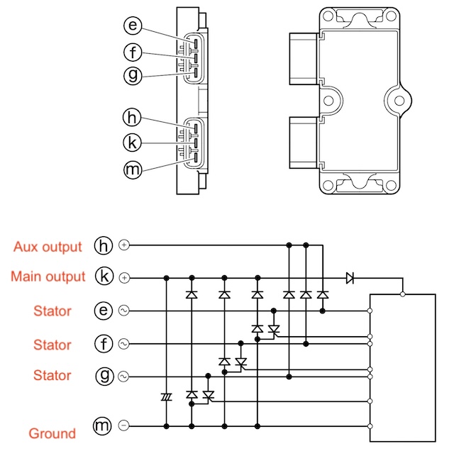
I'll let the engineers and technicians figure it out. But since replacing my regulator/rectifier did not rectify the problem , I am thinking about another option. I have access to a DC to DC charger and wondering if I can just connect my alternate charging lead to the input of that, and then connect my house batteries to the output. My assumption that the charger would regulate the voltage to a more appropriate level. Oh, and I did record the voltage output of both my regular charging system and the alternate system at various engine RPMs. The short of that being, the regular system put out anywhere from 14.37 to 14.67, while the alternate lead was putting out anywhere from 14.69 to 15.16. The weird thing is the alternate system, when the battery was removed from it, would put out 13.20 vts at idle, but 12.7 at 1600 rpm... No, I didn't reverse that. Higher rpms lower voltage... Colby |
|
| Back to top |
|
|
WCF
Joined: 21 Feb 2023
Posts: 99
City/Region: Central
State or Province: WA
C-Dory Year: 2007
C-Dory Model: 25 Cruiser
|
| Posted: Mon Aug 12, 2024 7:15 pm Post subject: |
|
|
Colby,
You can see in the schematic above, and confirmed by schematics I found with a quick google that the source is the same for both the "alternate" and the primary charging lead - The Stator. The stator (pictured in individual phases) is driving both the alternate/auxiliary charging and the main output.
The only point of this system (and the pictured diodes) is to have two charging circuits that won't feed back into one another.
I would run both wires to one start battery, and also have both batteries tested. I may not have all the information, but it doesn't seem possible that you'd see drastically different charging voltages on two healthy flooded or agm batteries that are not currently under load.
The two outputs are literally sharing opposite sides of a 3-phase AC waveform, I don't see a way they could be performing differently unless there's a problem downstream. This is reinforced by the fact that you replaced the regulator-rectifier and there was no change. |
|
| Back to top |
|
|
colbysmith
Joined: 02 Oct 2011
Posts: 4968
City/Region: Madison
State or Province: WI
C-Dory Year: 2009
C-Dory Model: 25 Cruiser
Vessel Name: C-Traveler
Photos: C-Traveler and Midnight-Flyer
|
| Posted: Mon Aug 12, 2024 8:10 pm Post subject: |
|
|
| WCF wrote: | Colby,
You can see in the schematic above, and confirmed by schematics I found with a quick google that the source is the same for both the "alternate" and the primary charging lead - The Stator. The stator (pictured in individual phases) is driving both the alternate/auxiliary charging and the main output.
The only point of this system (and the pictured diodes) is to have two charging circuits that won't feed back into one another.
I would run both wires to one start battery, and also have both batteries tested. I may not have all the information, but it doesn't seem possible that you'd see drastically different charging voltages on two healthy flooded or agm batteries that are not currently under load.
The two outputs are literally sharing opposite sides of a 3-phase AC waveform, I don't see a way they could be performing differently unless there's a problem downstream. This is reinforced by the fact that you replaced the regulator-rectifier and there was no change. |
Everything is as I described it. Weird! My concern has been that I believe 15.x volts is to high of a charging voltage. I can just leave the aux output out of the system, but I would really like to just leave my main battery switch on the start battery, and have the aux system charge my house batteries. I've given up trying to figure out why the aux lead is putting out more voltage with the battery connected, and now thinking of putting a DC to DC charger in line with that circuit to the battery. Thought process that a Victron 18 amp 12 v to 12 v dc charger would regulate the voltage and do a better job at charging my house batteries anyway. BTW, all grounds are good and all batteries are tied together as far as their negative post goes. Colby |
|
| Back to top |
|
|
WCF
Joined: 21 Feb 2023
Posts: 99
City/Region: Central
State or Province: WA
C-Dory Year: 2007
C-Dory Model: 25 Cruiser
|
| Posted: Mon Aug 12, 2024 9:57 pm Post subject: |
|
|
Weird indeed. I am sure I am missing something in understanding how the system works.
You mentioned seeing the appropriate charging voltage when both outputs are tied to one battery: I see no reason not to do that. You could then fully isolate the start and house batteries with a DC-DC in between the two batteries.
This weekend I finished installing a combination DC-DC and solar box (Renogy DCC30S), plus a combination inverter charger (Victron multiplus) and moving/installing LiFE4PO house batteries to the hot water cabinet, along with moving all of the house wiring and fusing. A lot of work. |
|
| Back to top |
|
|
|
|
You cannot post new topics in this forum
You cannot reply to topics in this forum
You cannot edit your posts in this forum
You cannot delete your posts in this forum
You cannot vote in polls in this forum
You cannot attach files in this forum
You cannot download files in this forum
|
|
 Search
 Private Messages
 Profile
 Log in
 Register
 Help
Help
