LuckeCatanias
Member
- Joined
- Apr 17, 2025
- Messages
- 41
- Reaction score
- 8
- C Dory Year
- 2005
- C Dory Model
- 25 Cruiser
- Hull Identification Number
- CD025115D505
- Vessel Name
- Pearl (formerly Daydream)
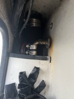
It's a good question!Are you sure that those pads are not going to cause stress points and deform the tank? It appears that large areas of the tank skin will be unsupported. For instance, roto molded water tanks are supposed to be supported at least every 2 inches.
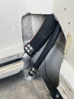
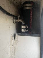
Probably the most direct, easy to understand reasoning is that this support spacing is (as Pat points out) no worse than what the tank (and likely all 100 gallon aluminum tanks in 25's) have. That is, a couple of rubber strips spaced about 24 inches apart.
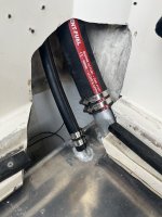
Here, not only is that spacing reduced, we have additional supports at the outboard-most ends of the tank.
The supports are also placed on or near the location of the internal baffles -- that makes the local section of the tank extremely strong.
I'll just point out too that roto-molded tanks may not be the best comparison -- plastic/hdpe has about 1/10 the strength of aluminum depending on what it is you are considering.
 ️
️