help wiring with shore power breaker

Jake B

New member
so I cut in the breaker box blue sea 120volt main with 2 15 a rocker.

I have red the instructions ( it was a few weeks ago and at work right now). but even when I read it wasn't really making all that sense to me. I am not the best when it comes to electrical. and have not really ever dealt with home electrical especially.

what I am wanting to do is this.

the boat came wired with two outlets and it looks like power comes into first plug and then back out and onto plug number 2 behind helm seat. when this was put in they just hard wired it. my hope it "cut" this box in before the first outlet and run both of them off one 15 amp breaker. leaving the second one open for me to add my battery charger later this summer once I decide how I want to do so.

I was kind of hoping if someone could help me out with this.. hopefully someone who has installed one or someone with a better understanding of electrical.

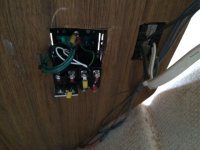
this is the backside of the existing electrical switch
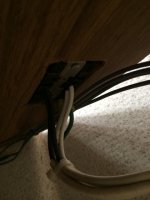
photo_7_001.sized.jpg

new box next to it
photo_6_001.sized.jpg

new breaker and old outlet (I am replacing outlets also when I rewire..
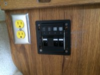
photo_8_001.sized.jpg
 
First this does not appear to be an original equipment installation. There is no ground fault interruption circuit. You can use one of the 15 amp breakers for two 15 amp plugs, but the total amount of current used by the two plugs can not be more than 15 amps. For example you cannot run a 12 amp heater off one, and a 12 amp electric frying pan off the other.

Second you need to make a number of changes. The connections could be in boxes which cannot be accessed from the outside--enclosed, so no terminals are exposed. I used the blue boxes as are used in household wiring, but metal boxes are also OK.

You need to have the two 15 amp plugs in series, hot (black) to the first box,which is a ground fault interrupter plug, and then the second plug in series. Same for white and green wires. Use the stranded marine wire, and crimp on connectors-you should also be using adhesive heat shrink over each butt connector and each ring connector.

The second circuit can be dedicated to your battery charger--and again there should be no exposed connections which might be touched by any person on the boat.

Here is an explanation and conforms to ABYC:
http://assets.bluesea.com/files/resourc ... Faults.pdf
 
thanks for the response and I Plan on putting Blue boxes on these as well. I Knew about the 15 amp to both would need to be watched and may just end up giving each one there 15 amp breaker. for us the main things that will be used is hair stuff dryer ect. for the wife and maybe a dvd player or lap top we don't really have much more of a use for shore power other than that and the main reason is to have a way to get batterie charger plugged in and keeping them topped off. I will read more about the putting them in series. thanks

also when i said original I just assumed it came that way, but this is how it was installed when i purchased the boat.
 
so after reading that link you put up is what i have considered a gfci? Sorry as this is kind of like reading something in broken english for me. I am much better visual learner. I will keep reading up on it as I want it done right.
 
so after looking at the wiring scheme online it looks like from the shore power receptacle. there should be a hot and a neutral coming off of it and they plug into the hot and neutral screw ends on panel.
then there are the 2 ac load output leads for each 15A breaker.

then it looks like the grounds come off the DC side? to a bush bar? this is where I am having a hard time figuring out how it goes this and then also the green wire?
this is the scheme I am looking at
http://assets.bluesea.com/files/resourc ... 343500.pdf
page 6

then i see this one also and it looks like you tie in the dc over to the ac eliminating the need for a bushbar?
http://assets.bluesea.com/files/resourc ... 343760.pdf

also the instructions don't talk a lot about ac install they go in more about dc.
and finally it will be less than a 10' run from shore power to box and 90% of the time the boat is on a trailer only moore if were staying on it.
 
aurelia thanks for the links yeah those are the outlets I am going to be installing. and may for now just put the one in next to new panel as I don't think we really need two outlets, and the one behind seat is hard to get anyways. still debating about that though..
 
Jake B":gsg3lhgb said:
aurelia thanks for the links yeah those are the outlets I am going to be installing. and may for now just put the one in next to new panel as I don't think we really need two outlets, and the one behind seat is hard to get anyways. still debating about that though..
If you wire them correctly, one gfci outlet can protect another std. outlet. E.g. if you wire the second outlet inline with the first, then if there is a current imbalance between hot and neutral at either outlet, the GFCI will trip. If the GFCI trips in this situation, both outlets will go dead as the second one is a "load" on the first one and is fed from the load side of the first. Alternatively, you can wire them both in parallel to the hot and neutral from the source. In this case you need a GFCI at both locations. IMHO, the only reason to do this is when the GFCI's are far apart (like in two separate rooms in the same house). For a boat a single GFCI protecting the other outlets is fine as it's easy to find the GFCI when it trips.
 
Aurelia":1qn2i3mx said:
This would be an example of an outlet based GFCI unit.

http://www.newegg.com/Product/Product.a ... 17162126:s

They also can be had in box form or inline form.

I use one like this from Home Depot

http://www.northerntool.com/shop/tools/ ... _200315305


Ground fault protection is even more important on a boat than in your house---the chance of an accident is more likely due to h2o being ever present. (Granted not having it around a bath or sink would be just as dangerous!!!! GFCI's are required by both land and marine codes and protect in other situations than those I've mentioned. The second gfci papparatus ( northern tool) will do the job just fine but is reliant on being used, ie. it is too easy to bypass when in a hurry or by someone else who doesn't know about its importance. It would be good to have for use when a "permanent wired-in GFCI unit isn't present". I would use the first example (shown: newegg.com or similar) and wire it so all downstream outlets are protected on a boat.
 
Jake B":17djyw7n said:
so after looking at the wiring scheme online it looks like from the shore power receptacle. there should be a hot and a neutral coming off of it and they plug into the hot and neutral screw ends on panel.
then there are the 2 ac load output leads for each 15A breaker.

then it looks like the grounds come off the DC side? to a bush bar? this is where I am having a hard time figuring out how it goes this and then also the green wire?
this is the scheme I am looking at
http://assets.bluesea.com/files/resourc ... 343500.pdf
page 6

then i see this one also and it looks like you tie in the dc over to the ac eliminating the need for a bushbar?
http://assets.bluesea.com/files/resourc ... 343760.pdf

also the instructions don't talk a lot about ac install they go in more about dc.
and finally it will be less than a 10' run from shore power to box and 90% of the time the boat is on a trailer only moore if were staying on it.

You will NOT tie the 12 volt negative, and the 110 volt green wire together in this project. (There can be a common point in some boats, with a bonding system--but you do not have this.) What you are confusing is the 12 volt negative (and positive) on the 110 V panel, for the LIGHTS, with the 110 volt circuit. The 12 volt DC on this drawing is only for the back lights on the circuit. You do not need or want this.

From the first breaker, take the white wire to the silver terminal, the black wire to the brass color terminal and the green wire to the green terminal on your first plug--which is a GFCI plug. Then take another white wire to the silver terminal to your second non GFCI plug, a black wire to the brass colored terminal, and a green wire to a green screw terminal.

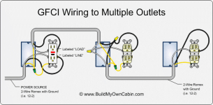
The diagram below is correct, except you are adding only one plug, are starting at the panel, and you are using butt connectors and ring connectors, not wire nuts (never use wire nuts on a boat). Each plug will have two screw connectors on each side of the plug--use one in for the GFCI plug, and the other out. This way, the second plug is protected by the GFCI. In this diagram, the yellow is your green wire.

cRLPX.gif
 
thank you for that break down! I will have a look at the panel tonight and that was where i was getting confused was all the 12v stuff but you are right i do not want the lighting hooked up.

this should be fairly simple then since the exsisting plugs are wired with all three colored wire I should be able to un hook first plug power in and run it through panel and then out to new gfi outlet.
 
You are going to have to change the route of the wiring. input to boat, then to panel, then probably same wire, but different sequence--first to GFCI plug, then non GFCI plug. Be sure that wires are all correctly hooked up. If you switch the black and white, it will be reverse polarity and will blow the GFCI. Also it has to be wired correctly at the plug (Home or marina), as well as all thru the boat.
 
we have used the current set up at friday harbor when we first got the boat and before i knew i needed this box and it worked fine so i am assuming It is correct wired. once I wire it if i am not sure it is correct i will post it back onto here. Plan on doing this week or weekend.

also the bush bar they included with the panel i do not need to use this correct?
 
Back
Top