House Battery Monitoring

John S

New member
Was wondering what some of the other C-Dory boaters are doing to monitor their house batteries. We have two Interstate Deep Charge (class 24? I think) batteries wired in parallel and we make 3-5 day trips. How well can you do watching your voltage level, I'm assuming not accurate enough, as the deep cycles are built to hold their voltage until close to death.

I'm looking at the Link 10 from Xantrex?
255200.jpg


You can see more on it at West Marine
http://www.westmarine.com/webapp/wc...attery monitor/All_2/mode+matchallpartial/0/0
Has anyone ever installed one of these? How much trouble is it. I don't want to rewire the entire boat like some of you guys like to do.

So what do some of you folks that make overnight trips (without shore power and generators) do to know where you're at on your battery charge?

John
 
I have used both the Link 10 and earlier predicessors which were multibattery with a large inverter charger. The advantage of the Link is that they give a good picture of the amount of current used, and replaced. Good monitering units for one battery.

I choose to use the Blue Seas single battery unit--and then put in a switch to read the voltage of 4 different batteries--two start, one electronics and one house. The Group 24 is a relitatively small battery--The 24 refers to the case size. There can be a spectrum of capacities of a group 24. Deep cycle does not really hold the voltage down to lower amount of discharge--this is pretty much of a given 12.2 volts steady state for 50% discharge (AGM is closer to 12.3 volts for 50% discharge). The heavier plates of deep cycle batteries, have slightly more amp hours and can withstand more cycles of discharge and charge.

I choose the two decimal point volt meter, with a lot of experience of battery monitering (and a separate rough amp meter)--but for the average boater and a single house bank, consider the Link 10. It is fairly easy to install--you have to be sure that all of the negitive power to and from that battery goes thru the one cable--and no bypass circuits--on this cable, you put a shunt, then a couple of sense wires. Plus hookups to the battery--not really difficult.
 
I'm a Link 10 believer, been using them on last three boats and also on our camping trailer. Real peace of mind. On my CD25 I have one for each of the two batteries, not much cost difference from the dual battery unit and I don't have to switch between them to view both -- just convenience.

As far as installation, you'll mount a 4" brass shunt (supplied) along a bulkhead near the battery which will monitor ALL of the negative post current into and out of the battery. If there are a lot of circuits going to that post, best to add a suitable terminal block to parallel the negative circuits. There are just a few small wires that lead from that shunt to the meter, you can buy a kit from Xantrex or just buy a generic multi-wire, stranded cable of the wire size they recommend (18 or 20 awg if I recall). Not difficult. Routing the wire from the stern to the dash is probably the hardest part, at least for me it was.
 
A couple questions; Is the link not appropriate for monitoring two batteries wired in parallell on the same bank? Do I need one for each battery :( I currently have two house batteries and am considering adding a third house battery with cables running to my only empty battery shelf left in my other pontoon. (it would all be on the same bank)
So Bob, you only monitor your voltage on ThatAway? , I've seen the picture of your selector?

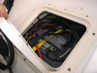
I am VERY concerned about where to mount this shunt or a terminal block, space is TIGHT. See my photo:
John
IMG_5467.sized.jpg
 
John S-

I believe you can use the monitor for two or three batteries wired in parallel, but only if you insert the shunt in the outgoing negative wire that carries all the combined electrical flow. Put another way, it must be in series with the combined three batteries with all the negative electrical current going through the shunt.

Then too, you'll have to set the amp hours in the monitor's memory to the combined two or three battieries' capacity. This assumes that the monitor will accept the added up total.

If space is tight, you can put the shunt in the negative lead anywhere, as long as all the current runs through it. Once the lead branches out, it won't work because there's more than one path and the shunt won't have all of the current flow running through it.

(Sorry to be so wordy, but it may eliminate some misunderstandings!)

Joe.
 
Yes, all of the current must go through the shunt in order for the Link 10 to properly monitor the current in and out of the battery or bank of batteries. Parallel the batteries then put the shunt in series with the lead heading to the loads -- and the charging source (motor); that's right, the outboard must also be connected so that the charging and starter currents (same cable) goes through the shunt.

The shunt generates no measurable heat, it is mounted only to stabilize the small wires connected to it that go to the meter. Therefore, you could probably figure out a way to shrink-wrap, tie-wrap or otherwise stabilize the wires to follow a cable bundle until it joins the pack going to the cabin.

One final comment, I generally don't like paralleling batteries. Each battery has slightly different characteristics (internal resistance, charge/discharge efficiency, etc), which leads to the possibility as they age that they will 'fight' each other and could actually boil the electrolyte/water solution right out of one of them. I've seen it happen. A better way to gain capacity is to place two large 6V golf cart batteries in series, then there's no possibility of electrical incompatibility or contention. Just my 2c.
 
Interesting that all the negatives must be brought together, it makes sense. But.....

My negative leads are:
-Outboard starter
-Jumper from Port Starting Battery (Only switched on during starboard battery jump off to start starboard motor)
-Cable to accessories at the dash
-Pot Puller
-Cable to parallel wire the batteries
-Windlass

Would it really be possible to gang these all together and connect them to the shunt? Is there enough room? I have both negative threaded terminals on the batteries pretty well loaded up to the highest level I feel comfortable, as it is. The photo above is pretty self evident. Would it work?

Steve, I understand your concerns about batteries, somewhere I read, maybe in the C-Dory manual, that the deep cycle house batteries should be replaced at the same time when wired this way. Undoubtedly, one will go out before the other some day though.
 
John S-

"Would it really be possible to gang these all together and connect them to the shunt? Is there enough room?"

This is a mechanical problem to overcome. We have described what must be done for the electrical device (Link 10) to work. Wheather it's practical considering the physical/mechanical difficulties involved with the limited space is your decision.

I'd try to connect all the leads you mention above to a very large bus, and then connect a line from the bus to the shunt, then more lines branching out from the other end of the shunt to the batteries. Won't be easy.

Maybe there's another solution that would be more practical in your situation?


*************************************************************************
For those interested, the shunt/Link 10 works like a recording/calculating ammeter and therefore becomes a battery monitor.

The shunt wired in series is necessary to measure all the current flowing into and out of the batteries. Almost all of the current runs through the shunt with it's very low resistance.

The meter (Link 10), is connected in parallel with the shunt. It has a very high resistance. If the shunt has a resistance of 1 ohm and the Link 10 circuit 9999 ohms, then 99.99% of the current runs through the shunt, and 0.01% goes through the Link 10.

The Link 10 knows this ratio (9999:1), and calculates the real current flow.

It then compares the cumulative current flow in and out of the batteries with the known amp-hour capacities (which you set) of the batteries to show you the remaining amp-hour capacity.

It also shows you battery voltage which is also a function of the state of charge.

Note that this is a somewhat over-simplified explanation of what must be happening, but it allows you to better understand how the Link 10 works.

Hope this is useful.

Joe.
 
Joe, yep, you got it. Hey, maybe you and I could open up a side business selling Link 10's and provide after-sales service installation tips, etc?? Hmmmm.

One more tidbit on the shunt. It is a bar of brass, very low resistance. Across the length between the screws that go to the meter, 500 amps of current produces 50 millivolts of voltage. Thus, the current is translated to voltage linearly. 5 amps produces 1/100th of that voltage or 0.50 millivolts (500 microvolts), and so on. The meter is essentially a computer that senses this current continuously, and the voltage AT THE BATTERY TERMINALS (no drop due to any loads except for the battery's internal resistance). These current and voltage measurements are integrated over time to measure the power being consumed or injected continously. We could go into Purkert's equations and battery efficiency in the next lesson...unless you've already gone to sleep!
 
Sea Wolf":17gsreyt said:
"Would it really be possible to gang these all together and connect them to the shunt? Is there enough room?"

This is a mechanical problem to overcome. We have described what must be done for the electrical device (Link 10) to work. Wheather it's practical considering the physical/mechanical difficulties involved with the limited space is your decision.

I've never seen the shunt, mechanically I don't know what it can handle. All I get is a pretty picture of the face of the device. Although ultimately it is my "decision" I REALLY hope a TC24 owner or previous owner has already come up with a solution to my tight fit, highly loaded battery terminal situation and will post the practical solution. (preferably without taking over the fish box) :D

I appreciate the better understanding of how a Link 10 works, it's nice to have it narrowed down to a quality product to get the job done. Now I just need a 24TC owner or two who have intstalled one to help me wrap this up so that I can place my order.

John
 
I did a little searching, this certainly seems to be what I need, the one with the 5/16 studs, now figuring out where to mount it.
John
21209_0.jpg
 
I had a link 10 on the sailboat, and it worked great. However the price has doubled to ~$200. I now use an analog voltmeter ($20,) with an input switch. When the voltage gets down to 12 vdc, time to recharge. Connected directly to each battery bank, so the reading is at the battery and no bus bar is needed.

Does anyone know where to get the equivilant to a link 10 at ~$100? That would make it worthwhile.

Also, Interstate deep cycle batteries are good for about 200 cycles, 9 mos at a daily cycle. I found this out the hard way. I switched to golph cart batteries, which one can install on a CD25. Any other deep cycle battery suggestions?

The southern Boris
 
I am also really big on Golf carts--We have had them in the Cruising sail boats and trawlers and RV's. Usually 3 to 4 groups of 2 6 volt batteries. However in the C dory and Tom Cats, this puts a lot of weight aft--and we have elected to have at least one AGM group 31 foreward (may have two). I don't have a probelm with two similar type and age (for example if I had two lifeline AGM of approximately the same age, the interaction is minimal)

I agree with the buss bars you have pictured--exactly what we have used--get the one with the small terminal strip and two 5/16 or 3/8 studs on the ends. You should be able to find some area which is only 3 x 5" for this terminal strip and shunt. You may want to mount a piece of wood in this area, and then take the single cable from the battery to the shunt, then the buss bar, and all of the other wires off the buss bar. I have a friend with a 24 TC down the street and probably could ask him where to put the buss bar.
 
I discussed this with my neighbor (and maybe he will chime in here) who owns a Tom Cat 24. He feels that if you take out the battery, and stick your head in there (His words)--that you will see that there is room for the shunt and buss bar in the lazarette area. Hook up the shunt and buss bar, then put the battery back in--with only one cable to the positave and one cable to the negitive buss bars/shunt.
 
Bob,

This is good news, I was hoping to hear some TC24 guy had figured it out. Could you get him to be more specific about how and where he mounted it in there. I'm still new to screwing and drilling fiberglass and still trying to figure out what to bolt all the way thru with a backing plate and what things I should use a screw for. Do you know if he found room for both a negative and positive buss?

Moving on to the necessity of the Link 10. How many of you guys think just watching the voltage level is accurate enough? I know the 737 I fly just has a minimum battery voltage specified for starting the Auxiliary Power Unit (APU). Can this principal be used on my boat also. "The Southern Boris" you have used both the link 10 and just watching the voltage. Did you find a direct correlation between a specific battery voltage and the state of charge on your batteries when you were using your link 10?

Bob, I'm not sure I understand exactly what you are using now, are you monitoring voltage ONLY at this point on your boat with your rotary switch?

If lots of people are finding voltage monitoring sufficient (although not specific) I would rather spend the $300 or so in monitor, busses and wiring toward a Honda 1000W generator instead, which I think I will end up needing anyway.

Thanks for all the help,
John
 
John,

I regularly have kids (big now) on board. We occasionally watch a DVD movie, and they sometimes are allowed to play video games for a few hours. Other than that, we have lights at night, stereo, GPS/tide monitoring sometimes, VHF chatter sometimes, Wallas heater (miniscule current) -- and that's about it for the most part. No refer, I have an extra insulated ice chest that lasts ~5 days which is adequate for 95% of my trips. I only have 2, 110 amp-hr batteries (KISS and weight), they do fine for my lifestyle.

I never run my batteries below about 70% of their capacity (1 at a time), 50% is the recommended maximum to discharge before damage. 70% x 110 amp-hrs is 77 amp hrs. Therefore I can use 33 amp-hrs before recharging or switching batteries. For my energy needs, that's sufficient for several days. And usually we go somewhere in the boat, so it recharges after a few days anyway. If not, I throw a 30 watt solar panel on the roof and it brings back 20 or more amp-hrs on a sunny day.

Voltage monitoring is approximate at best for determining capacity remaining. While draining the battery, the voltage will give a falsely lower reading, mine is regularly at 11.8V or even lower during 4-6amp drains (DVD, TV). Temperature also affects the reading. After a 2 or more hour rest with no draining, you CAN get a feel for the % capacity remaining of the battery, especially as you gain experience with the readings. But being an approximation, you might have quite a bit of useful energy remaining while you're panicking over the reading, or conversely, you might be very close if not beyond what you should have used in order to have enough to turn over your engine on a cold morning.

I'm an electrical kind of guy and I have great peace of mind knowing exactly what's happening with my batteries and my emergency ability to use the VHF radio or start the engines. And sometimes I'm surprised to find an unexpected current drain when I check the amperage before leaving the boat or going to bed -- something left ON (usually the VHF). For me, it was one of the first accessories to be installed on my boat!
 
Steve, Some very interesting thoughts. I am surprised how much use you are able to get out of two smaller batteries on one charge. I haven't sat down to run all the numbers on all the different accessories we like to use while sitting at anchor, I probably should. So far it has all been a guessing game. It sounds like you went at battery monitoring the same way I went at a fuel flow meter. The navman 3100 was my first installation, for the same reason as your Link 10, piece of mind. Some good points, thanks. Which solar panel are you using? where did it come from? do you get any charge on a cloudy day? not much sun in coastal AK.

Thanks,
John
 
John,

Yes, I'm able to squeeze quite a bit of usage out of my batteries. I usually only use one battery for house power on a trip, next trip I use the other. That way I always have a fresh battery to start at least one engine. I had a dead battery one time at launching, wouldn't start the engine (long story why it was dead). I started the other engine on its battery, then after a short warmup, switched to BOTH, waited 5 minutes, then started the other engine. I have Yamahas with 20 amp output, other engines may not be recommended for that trick so check your manual first before trying. It's fascinating to learn just how much or how little each accessory uses as you turn them on/off one at a time. Stereo, GPS, Wallas heater (after turn-on sequence), VHF (idle) are all surprisingly low -- less than a light bulb! The windlass under a strain uses 25-35 amps, but I supplement that with one engine revved to 1500 rpm or so while bringing up the anchor.

I forgot the name of my flexible solar panel, bought it at West Marine about 15 yrs ago, haven't seen that brand there lately. Not as efficient (size vs output) as rigid panels, but it sure is easy to store under my front bunk and deploy on my roof when needed (plugs into dash 12V receptacle). It's about 1/4" thick, maybe 18"wide by 5' long. I always smile when I see a PLUS amperage number on the meter while I'm running the stereo maybe while eating breakfast -- running on the sun and recharging my battery to boot!

Next accessory: Fuel flow meters!!! Probably Navman, still in research mode...
 
John,
I did not say that my neighbor had put in a shunt or buss bar, but that he felt that there was room,if you took out the battery--on the side. There are many ways to put in electrical elements. I prefer to screw the buss bar and other accessories onto a pressure treated piece of wood, and then bolt or screw that piece of wood to the fiberglass. This way, you can rig the circuits on the board, and then put the board in after all rigged. If you need to change, just unbolt/screw the board and take it out into the open.

Yes, I have a single digital volt meter, with a 4 battery bank monitering circuit. I have used the Link and similar systems. But I also have over 45 years experience with 12 volt battery power management in boats. Some of this included crossing oceans under sail alone, with full navigation equiptment, Nav lights for 10 or so hours, SSB Radio daily, Weather Fax several times a day, and an auto pilot running full time. After awhile you develope reflexes and know rather closely how much power you are using. I measure the voltage on the battery banks, after most power sources are off for half an hour, and determine how much I have to charge.

In the C Dory22, I had no power management--only two group 24 batteries--one engine start and one was "house" wired directly to the Wallas. I carried a garden tractor (AGM) spare--it would start the engine in an emergency. For the Tom Cat 255--there are far more electronics and "gadgets" than on the C Dory22. There are two battery banks for the house--plus two engine start batteries--any one of these would run the boat--except for the freezer--and that will usually be run off one bank. I will just do the same as I did in the sailboats and check battery voltage in steady state--and be sure I don't go beyond the 12.2 volts discharge level, and then charge appropiately. I have a Honda EU 2000i and 44 amps of charging capacity on each of the engines. I had a Link on my last boat--and frankly, didn't use it, except as a battery volt meter.

Will the link give you more information? Absolutely yes. Is it essential--that is debatable. But if you are more comfortable with it--get one.
 
thataway":2pq4yv46 said:
John,
I did not say that my neighbor had put in a shunt or buss bar, but that he felt that there was room,if you took out the battery--on the side.

Bob, thanks for clearing that up.

Well, very interesting discussion that has really left me undecided. C-Dory set the TC24 up with a starting battery dedicated to ONLY starting the port motor. All systems and starboard motor are powered by a starboard deep cycle battery, I've added a battery, so two. The Port side battery is kept isolated from EVERYTHING else, there is a jumper switch for starting the starboard motor if it is dead.

So...killing my house batteries shouldn't be an issue for starting when things are going bad. I'm not familiar with other C-Dory's setup, but I really like the redundancy.

I don't want to kill house batteries, to extend their life, but in theory it's not like the link 10 will keep me from stranding myself with nothing to start a motor with.

So undecided it is.

Thanks for a great discussion guys, I have a much better understanding of my house batteries now.

John
 
Back
Top